Having some odd electrical issues

TL;DR: I think I might be encountering two separate issues… a faulty switch chip and a bad clock signal.

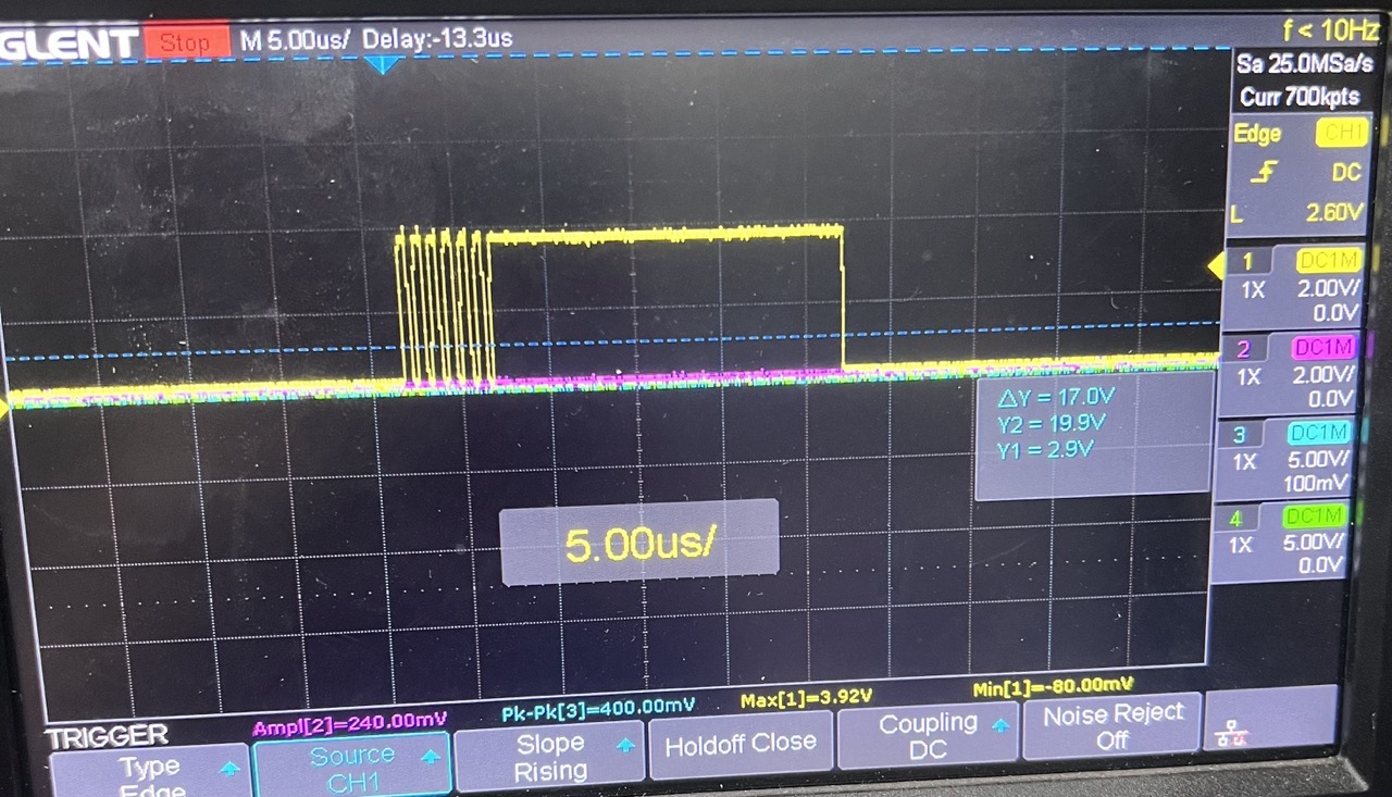
I got my Jumperless kit yesterday and assembled it without issue. I checked it under a magnifying glass and didn’t see any stray solder or bridges. I flashed the latest firmware and made a sample Wokwi project, just connecting a couple rows. The LEDs lit up to show the connections, but the actual connections weren’t being made (no continuity when checked with a multimeter). I cleared the netlist and checked each row against power and ground. Row 32 showed a steady -8.68V, and row 34 showed a flakey -3.1V (both connected to switch chip E). I looked through the schematics and PCB layout and didn’t see anything that could short to cause that, so I lifted switch chip E pin 35 to disconnect row 32, figuring I could still use it and just avoid that row. I plugged the board back in and tried again, but still no luck making connections. The power, ground, and reset for each switch chip checked out fine. Checking clock and data with an oscilloscope revealed that the data net was fine, but clock net was not working properly. Rise time was good but fall time was extremely slow, so I don’t think the switch chips were actually seeing clock pulses. Thinking that something else might be weird with switch chip E, I lifted its clock pin as well, but the behavior was still the same. It’s like the RP2040 isn’t actually driving the clock signal low.
Any suggestions for other things to check? I’m currently out of ideas :sweat_smile:


Hey Mitchel,

Yeah none of the rows should ever be showing -8.68V, there shouldn’t be any way for that un-diode-dropped negative rail voltage to get to the breadboard unless something has gone horribly wrong, which it clearly has. There’s a short somewhere or a fried chip that’s acting as a short to some net that’s connected to all of the matrix chips, and this other stuff looks like (hopefully) some cascading failure from that.

Edit: I just checked the CLK line on a working one and I was mistaken. The clock line is absolutely not supposed to look like that. You’re absolutely right that it look like it’s not being pulled down actively. Here’s what it’s supposed to look like:

So I think we should start with the fried chip.
Would you mind trying these things and letting me know what happens?

If you try to make a connection on some other part of the board, does a similar thing happen? Or is it just stuff connected to Chip E?

Do you read -8.68V anywhere else on the breadboard?

Do you have a hot air gun or a way to remove chip E entirely and see if anything is different?

We’ll get this figured out. I’ll pack you some spare parts and have those sent out tomorrow, or alternatively, an overnight shipping label where you can send it to me and I’ll fix it and send it back. Up to you.

And looking at the timing on your oscilloscope readings, yeah it looks like you have a capacitor on your CLK line somehow. That’s weird because here’s the net:

It doesn’t seem to get anywhere near a capacitor to GND.

My next guess would be PIO code to drive the pin but you’re running the exact same pre-compiled firmware as I am. So it has to be something in hardware.

Fried chips do a lot of weird things though, like act as random diodes between various pins, so let’s get that figured out first.

Thanks for the ideas.
I only saw -8.68V on that one row (and the VEE pins of the switch chips).
My hot air station is pretty basic, but I was able to remove chip E. The CLK signal is still behaving the same though.
Something I just noticed is that the CLK signal is showing open circuit to GND when everything is idle… I’m fairly sure that the RP2040 output driving it low should make it read low resistance to GND?

Yeah, it should.

Maybe try checking the clock line closer to the RP2040 to be sure it’s not a broken trace? Here’s the net near it.

And then try checking continuity between CLK and the other data lines, DATA, CS (all of them), RESET, etc.

Do any of the crosspoint switches get hotter than the others while it’s been on for a bit? If so, take that one off and check the CLK again.

Next thing I would do is to desolder the crosspoints one-by-one, checking the CLK each time to find the bad crosspoint that might be doing this.

Continuity across the CLK net looks good. No continuity to the other lines.
Nothing on the board shows up as getting particularly hot.

Out of curiosity, I added a 10k pulldown resistor to the CLK line and the signal looks reasonable. The crosspoint switches appear to be getting configured now as well, although obviously not all connections work with E missing. I didn’t test extensively, but I made a net for each crosspoint switch that had direct breadboard connections and verified all of those had connectivity.

EDIT: here’s the netlist I used
1-30, 30-31, 31-60, 2-3, 3-4, 4-5, 5-6, 6-7, 7-8, 9-10, 10-11, 11-12, 12-13, 13-14, 14-15, 16-17, 17-18, 18-19, 19-20, 20-21, 21-22, 23-24, 24-25, 25-26, 26-27, 27-28, 28-29, 32-33, 33-34, 34-35, 35-36, 36-37, 37-38, 39-40, 40-41, 41-42, 42-43, 43-44, 44-45, 46-47, 47-48, 48-49, 49-50, 50-51, 51-52, 53-54, 54-55, 55-56, 56-57, 57-58, 58-59


1 Like

Oh sick! Excellent hack/fix!

That’s fascinating that it worked, maybe some bad line driver in the RP2040 itself? Because there’s no external pulldown resistor on that line.

I’ll make sure to include the RP2040 in the hacked off chunk of board I’m sending you to use as spare parts. In case you ever get curious about what’s causing that.

Yeah, a bad line driver seems likely. Fortunately it’s just the low side, and that was pretty easy to work around.
Spare parts are much appreciated… I’m looking forward to getting this thing fully operational!

1 Like

Thank you for troubleshooting your board instead of sending it back and having me do it. I wouldn’t mind at all, but it’s really cool to have people who are willing to do that. And now you’re one of the few people on earth who have put some real effort into understanding how it works and how to troubleshoot the thing and can maybe help others with similar issues.

2 Likes

I got switch chip E swapped out, and I think my board is electrically in a good state now, thanks!

2 Likes