I’m reasonably comfortable with the Arduino IDE, and can build regular breadboard circuitry. I’m just starting out with the Jumperless (I LOVE the idea!), and have quickly realized I’m out of my depth. Just to experiment, I plugged in a new(ish) Nano and fired up Wokwi. I used the half breadboard and hooked up a virtual SSD1306 to what I believe was the +5V, GND, SCL (A5), & SDA (A4). I loaded up a standard display example. When I run the simulation in Wokwi, the simulated SSD shows the various patterns from the Adafruit sketch.
I started the Jumperless app, and copied the URL link into slot 0 and saved it. I believe I connected the Jumperless to the correct COM port (16, in this case). However, the Jumperless doesn’t seem to get the connection to Wokwi - no wiring or other changes I make in the simulator seem to come across. There are no changes to the LEDs on the Jumperless that would indicate the wire connections are made.
I’m sure there is some basic setup procedure that I have totally missed, but I’m unable to figure it out. I’m running Windows 11 Pro (64 bit). I’ve also tried to run the Jumperless Wokwi Bridge, but the error I get there is "Unable to connect to COM6: port not found
Process ended with exit code 1." I don’t see where COM6 is specified in the python code, so I don’t really know how to correct it. My guess is that the Bridge isn’t functioning, so my setup is incomplete. Any help or directions to further documentation would be greatly appreciated!
I’ll take a closer look at this when I get home in a couple hours, but you’re right that the issue seems to be with the app.
First thought about what might be happening, did you save the Wokwi example before you copied the URL?
When you first open the examples, it gives you a generic URL and then when you save it, it changes to a unique URL so all the changes you make are saved.
I thought I saved it before copying the URL, but I’m not sure. I’m going to recreate the project from scratch under a new name, and then load it into Jumperless (I hope!).
Will this do anything to correct the error I get when trying to run the Wokwi Bridge? I’m pretty sure that might be doing bad things (or not doing good things) at the moment, which may be the source of the problem.
Also, just so we can pin down whether the issue is with the USB connection or the connection to Wokwi, try this.
After you get through the startup stuff about saving a project to a slot, does a menu show up that looks like this? (You might have to type m and then enter)
Nothing happened.
Just as an FYI, when I restarted Jumperless the last time it showed 3 COM ports available (1, 15, & 16). It then showed the following:
Autodetected Jumperless at COM15
Autodetected USB-Serial at COM16
I think I read somewhere in the forums that you prefer Jumperless to be attached to the higher port number. How can I force that?
It should actually be the lower port number in general, but that shouldn’t be an issue anymore because it now selects the port based on which one responds with the firmware revision number. I’ll double check the code but the port autodetection should (most likely) be fine.
So what happens after that? Would you mind screenshotting (or copy pasting) the whole output from the beginning?
I have reconnected the jumperless board with a new Nano I had on hand.
When I start the app, I get this window - the app hangs with no further output after the autodetect lines. (This is new behavior, btw.) I’m beginning to think that Windows is being “helpful” in the background.
I’m going to do a reboot and come back here. Perhaps things will be clearer then…
OK, I’ve rebooted and started up the jumperless app again. Screenshots number 2 & 3 attached show where I’m at now. I’ve also included a shot of the sketch that’s simulated in Wokwi.
By having the Nano on the breadboard like that, it’s trying to connect every single row on the Nano to the row it’s plugged into, even if it’s not connected to anything else. It’s a known issue on the USB stack for the RP2040 where if too much stuff is being sent both ways at the same time, it ends up locked in a loop.
I’ll try to add some more safeguards for that tomorrow.
Also, you don’t need to connect power and ground on the Nano, those are hardwired on the Jumperless.
Try it like this and let me know if it works. Here’s the link to the Wokwi project, be sure to save it before copying the link into Jumperless.exe
Well, that’s a lot better, I think. Now I have LED’s lit up on A4 (SDA) and A5 (SCL) on the Nano connector, and columns 1 through 4 are lit up on the breadboard. On my Nano, the SDA is on A4 and the SCL is on A5, btw.
I couldn’t see the attached Wokwi project that you mentioned, but I don’t think that’s particularly necessary.
Now, I’m sure this is going to be a stupid question, but do I have to upload the sketch from the Arduino IDE to the Nano as well, or does Wokwi do the whole thing? The Wokwi simulation shows the code running the SSD display, but I don’t get anything on the SSD plugged into the Jumperless in exactly the same points. I tried to upload the sketch to the Nano from the IDE on COM16. It compiles OK, but won’t upload - I get the following rather unhelpful error:
avrdude: stk500_recv(): programmer is not responding
avrdude: stk500_getsync() attempt 1 of 10: not in sync: resp=0x55
avrdude: stk500_recv(): programmer is not responding
avrdude: stk500_getsync() attempt 2 of 10: not in sync: resp=0x55
avrdude: stk500_recv(): programmer is not responding
avrdude: stk500_getsync() attempt 3 of 10: not in sync: resp=0x55
avrdude: stk500_recv(): programmer is not responding
avrdude: stk500_getsync() attempt 4 of 10: not in sync: resp=0x55
avrdude: stk500_recv(): programmer is not responding
avrdude: stk500_getsync() attempt 5 of 10: not in sync: resp=0x55
avrdude: stk500_recv(): programmer is not responding
avrdude: stk500_getsync() attempt 6 of 10: not in sync: resp=0x55
avrdude: stk500_recv(): programmer is not responding
avrdude: stk500_getsync() attempt 7 of 10: not in sync: resp=0x55
avrdude: stk500_recv(): programmer is not responding
avrdude: stk500_getsync() attempt 8 of 10: not in sync: resp=0x55
avrdude: stk500_recv(): programmer is not responding
avrdude: stk500_getsync() attempt 9 of 10: not in sync: resp=0x55
avrdude: stk500_recv(): programmer is not responding
avrdude: stk500_getsync() attempt 10 of 10: not in sync: resp=0x55
Failed uploading: uploading error: exit status 1
Ah yes many thoughts on that. Mainly that I took out that functionality a while back because it was causing too many issues for people who weren’t using it and it’s kinda finicky for people who are. I was waiting for someone to ask before working on adding it again.
The much more foolproof way to flash the Arduino is to just plug it in with a second USB cable, copy your code to Arduino IDE and flash code like you normally would. It’s just much more reliable that way.
I’ll give the flashing from a single USB cable another look though, the issue is there are just too many options to reasonably ask a user to make it work for multiple boards in TUI. It’s really just running arduino-cli but I don’t want to make users craft a whole long command for that themselves.
OK, I completely understand why you don’t want to build in any more complexity than you have to! I’ll give the direct upload path a shot tomorrow - got to get up early for another task, so off I go now!
Thanks again for all your help - you’re very professional and patient!
Happy to report a qualified success. There were several intertwined issues:
I needed to select “ATmega328P (Old Bootloader)” as the processor in the Arduino IDE. I think that the Nano boards I have are older models.
I needed to roll back the driver for the COM port.
I found that even though I had connected the negative ground rail to column 1 and had the column LEDs lit up, there in fact was no ground path on that column (measured directly with my DVM). Moving all my connections to the OLED over one column to the right corrected that.
I printed the stand that one of your other customers created - it looks great!
It took a few tries, but now I feel a lot more confident that I can move forward and use this magnificent tool! Thanks again!
Judging by the Helvetica “Nano” label on that thing, it does look like an older model. That’s actually really cool, I don’t think I’ve ever seen one of those.
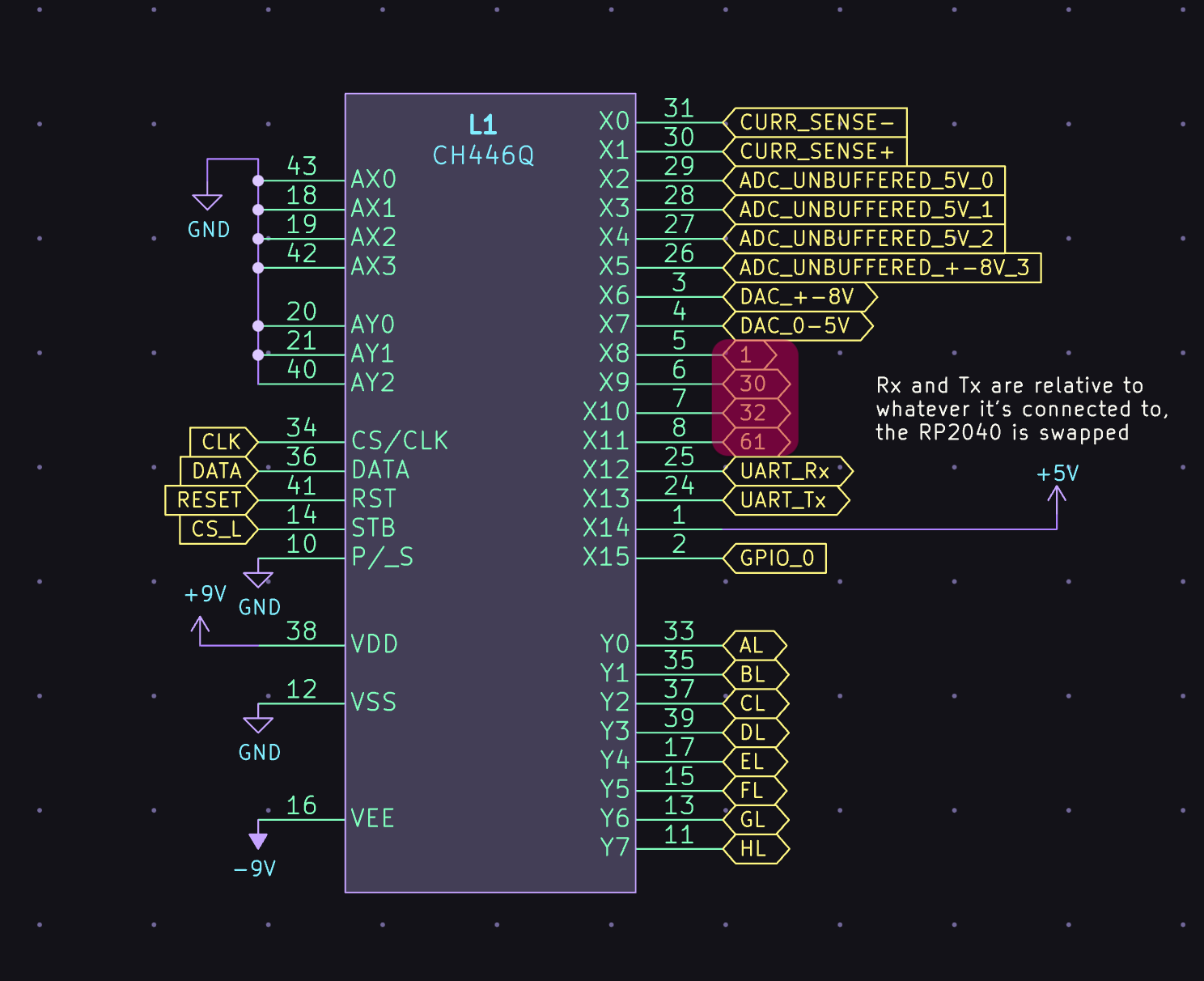
And yeah, I generally advise not using the 4 corner columns 1, 30, 31, and 60 if you can help it (really just for 3.3V and GND, anything else should work fine). The way the math works out means 4 rows had to be put on one of the “special function” chips.
I should fix the routing for those, but it would still need to make a couple of “hops” so the connection resistance would be higher.
And yeah that stand is great, I use it too. I made mine shorter by just placing it through the build plate in the slicer, and added some of the same stick-on rubber feet that are on the Jumperless. I’ve seriously been having trouble finding a way to improve it.
Let me know if you run into any more snags. I love knowing that people are out there using my thing.
One last quick question:
What is the function of the little slide switch in the upper left-hand-side of the board? It came with the switch in the center position, and I’ve left it there. I would like to know what will happen if I move it inadvertently…
Oh that sets the voltage for the power rails on the breadboard. It’s hard to read with the kinda mushy silkscreen, but here’s what that logo should look like:
The low position will put both the top and bottom positive rails at 3.3V, middle will be 5V, and the high will set the top positive at +8V and the bottom positive at -8V.
The Jumperless has no way of knowing where this is set, so in Wokwi, connecting something to the top positive rail will always connect it to the 5V supply, and the bottom positive rail will be the 3.3V supply.
Ah, I see it now that you point it out! I’m glad I asked… There’s no end of clever sh*t on this little miracle you’ve created!
I had to get graduated lenses a few years back (one of the myriad pleasures of living past one’s “best before” date), and ever since then I find I need strong magnification and bright lights to see tiny, low-contrast stuff. Sigh.
If it makes you feel any better, I’m 33 with unnaturally good vision and can barely read it. It’s really easy to lose a sense of scale when you’re designing stuff on a computer and can zoom in as much as you want.